DOWNLOAD SOFTWARE
FIRMWARE UPDATE
Type: Firmware
Version: 032715
Model:
458-CM-20
Filename:
458_Firmware_032715.zip
Size: 8 MB
Release Date: 04/2015
Instructions: Updating the Control
Module Firmware through the Serial Port
Please become familiar
with this procedure before attempting to reprogram a Control Module.
|
Step 1 – Verifying the Currently
Installed Firmware Revision
To check which revision of software is loaded on the
Telebyte Control Module, use the id command from a data terminal or a PC
connected via the RS-232 port.
To use the PC, use the HyperTerminal program. It can be found at the following locations:
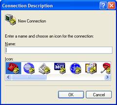
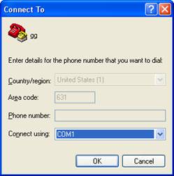
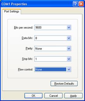
-
Select a baud rate 9600 (Bits per second) to match the
Control Module settings. Select databits
= 8, parity = none, stop bits = 1, and flow control = none and then press "oK."
-
Press enter and to confirm that there is communication. To send the
id command, enter "id"and
press Enter. The Control Module
software revision appears on the screen.
Note: After upgrading the software,
the echo command may become disabled and it may seem as if there is no
communication. To restore the echo feature, replace the id command above with
"ee" to send the ee command.
Step 2 - What You Will Need To Update
the Control Module Firmware
-
A 458-CM-20 inside a
458-CC chassis. This is the Control Module to be
updated.
-
A PC with an RS-232 serial port (e.g., com
port 1) and Windows 95 (minimum).
-
A standard serial cable to connect the PC
to the Control Module. (An example of this is a cable with a DB-9 male
connector on one end and a DB-9 female connector on the other end).
|
|
Step
3 - Obtaining New Software
- Download the software by clicking on the download button at
right. When the download window appears, click Save to begin the download process. Save
the zipped file to the desktop.
|

458_Firmware_032715.zip
(8 MB)
v 032715
Released: 04/2015 |
|
Step
4 - Upgrading the Control Module Software
-
Connect
the 458-CM-20 to the PC with RS-232 communication using the
RS-232 serial cable.
- The
458-CM-20 must be put into the BOOT LOADER mode in order to
upgrade the software.
- To initiate BOOT LOADER mode, first turn the power
off to the unit. Write down the configuration of the DIP slide switches on
the front panel. These switches must be reset after the upgrade is completed. Then
set all slide switches to the "ON" position.
This will allow the unit to be in the BOOT LOADER mode. Turn power to the
Control Module on.
-
The
DIP slide switches are the switches on the front of the 458-CM-20 Control
Module. See Appendix 1, later in this
document, for an explanation of how those switches are set for "normal"
operation.
Note: Normally, when power is turned on to the Control Module, the Error "light"
will blink twice. In the BOOT LOADER
mode, when power is turned on, the Error "light" will not blink.
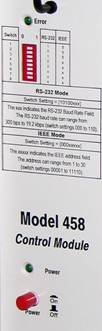
The 458-CM-20
-
Double-Click"458_Update.bat" to run the
update.
-
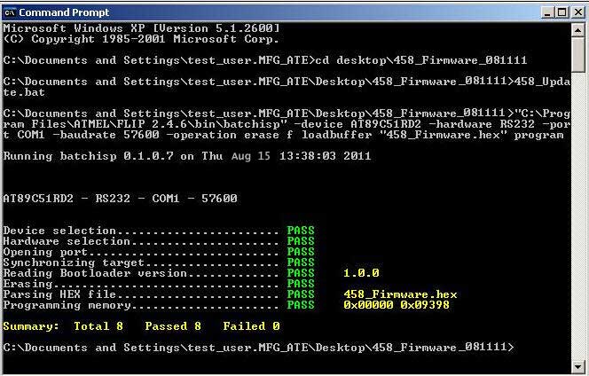
During the updating process, a screen
similar to the one shown below is displayed. When the
update is completed, check and verify that all of the tests show
PASS and none of them display FAIL.
-
If there is a test that displays
FAIL, contact
technical support.
-
If all of the tests show PASS,the
update is completed.
-
Type Exit and press Return to go back
to Windows.
-
Enter
458_Update.bat at the
prompt and press Enter. The MS-DOS batch file
program runs.
-
During the updating process, a screen similar to the one shown below is displayed. When the update is completed, check and verify that all of the tests show PRAS and none of them displayFAIL.
-
If
there is a test that displays FAIL,contact
technical support.
-
If all of the tests show PRASS,the update is completed.
-
Type
Exit and press Return to go back to Windows.
Step
5 -
Verifying Installation
-
Turn the Control
Module power off.
-
Return the DIP slide switches to the original settings recorded in Step 4.
-
Turn the power back on. The Error
light on the 458-CM-20 should blink twice.
-
You have
successfully updated to the latest firmware revision. The Control Module is now
ready for use.
-
It is
recommended that you verify your new firmware version when installation
is complete. Refer to Step 1 for instructions.
Appendix 1 – Control Module DIP Switch Settings
|
Switch
|
RS232 Mode
|
IEEE Mode
|
BOOT LOADER Mode
|
|
1
|
1
|
0
|
1
|
|
2
|
0
|
0
|
1
|
|
3
|
1
|
0
|
1
|
|
4
|
0
|
Y
|
1
|
|
5
|
0
|
1
|
|
|
6
|
X
|
Y
|
1
|
|
7
|
X
|
Y
|
1
|
|
8
|
X
|
Y
|
1
|
Where X is the serial baud rate and
Y is the IEEE address.
For the serial baud rate, choose one of the following:
|
Switch
|
19.2k
|
9.6k
|
4.8k
|
2.4k
|
1.2k
|
|
6
|
1
|
1
|
1
|
0
|
0
|
|
7
|
1
|
0
|
0
|
1
|
1
|
|
8
|
0
|
1
|
0
|
1
|
0
|
Combining the values of the switch settings as below sets
the IEEE address:
|
Switch
|
Value
|
|
4
|
16
|
|
5
|
8
|
|
6
|
4
|
|
7
|
2
|
|
8
|
1
|
|
